PA6和PA7是TIM3的通道1和通道2,我们计划用TIM3接编码器,所以需要接在PA6和PA7.
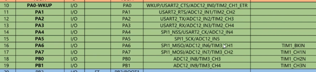
所以编码器的A、B相接在PA6和PA7
这次用到的函数比较少
void TIM_EncoderInterfaceConfig(TIM_TypeDef* TIMx, uint16_t TIM_EncoderMode, uint16_t TIM_IC1Polarity, uint16_t TIM_IC2Polarity);
定时器编码器接口配置,TIMx选择定时器,第二个参数选择编码器模式,后面两个参数分别选择通道1和通道2的电平极性
输入模式选择原则:
看外部模块输出的默认电平,如果外部模块默认输出高电平,我们就选择上拉输入,默认输入高电平,如果外部模块默认输出低电平,我们配置下拉输入,默认输入低电平。一般来说,默认高电平,这是一个习惯的状态,所以一般上拉输入用的比较多。如果不确定外部模块输出的默认状态,或者外部信号输出功率非常小,这时就尽量选择浮空输入。浮空输入没有上拉电阻和下拉电阻去影响外部信号,但缺点是当引脚悬空时,没有默认电平了,输入就会受噪声干扰,来回跳变。
首先我们海狮根据以上结构体来进行初始化:
RCC_APB1PeriphClockCmd(RCC_APB1Periph_TIM3, ENABLE);
RCC_APB2PeriphClockCmd(RCC_APB2Periph_GPIOA, ENABLE);
GPIO_InitTypeDef GPIO_InitStructure;
GPIO_InitStructure.GPIO_Mode = GPIO_Mode_IPU;
GPIO_InitStructure.GPIO_Pin = GPIO_Pin_6 | GPIO_Pin_7;
GPIO_InitStructure.GPIO_Speed = GPIO_Speed_50MHz;
GPIO_Init(GPIOA, &GPIO_InitStructure);
TIM_TimeBaseInitTypeDef TIM_TimeBaseInitStructure;
TIM_TimeBaseInitStructure.TIM_ClockDivision = TIM_CKD_DIV1;
TIM_TimeBaseInitStructure.TIM_CounterMode = TIM_CounterMode_Up;//计数方向也是被编码器托管了
TIM_TimeBaseInitStructure.TIM_Period = 65536 – 1;
TIM_TimeBaseInitStructure.TIM_Prescaler = 1 – 1;//不分频,编码器的时钟直接驱动计数器
TIM_TimeBaseInitStructure.TIM_RepetitionCounter = 0;
TIM_TimeBaseInit(TIM3, &TIM_TimeBaseInitStructure);
编码器接口会托管时钟,就是一个带方向控制的外部时钟,所以内部时钟就没有用了
TIM_ICInitTypeDef TIM_ICInitStructure;
TIM_ICStructInit(&TIM_ICInitStructure);//赋一个初始值
TIM_ICInitStructure.TIM_Channel = TIM_Channel_1;
TIM_ICInitStructure.TIM_ICFilter = 0xF;
TIM_ICInitStructure.TIM_ICPolarity = TIM_ICPolarity_Rising;//这里上升沿代表的是高低电平极性不反转
TIM_ICInit(TIM3, &TIM_ICInitStructure);
TIM_ICInitStructure.TIM_Channel = TIM_Channel_2;
TIM_ICInitStructure.TIM_ICFilter = 0xF;
TIM_ICInitStructure.TIM_ICPolarity = TIM_ICPolarity_Rising;
TIM_ICInit(TIM3, &TIM_ICInitStructure);
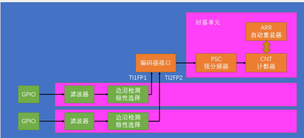
//由上图可知,输入捕获单元并没有完全使用到,编码器接口只使用了通道1和通道2的滤波器和极性选择,所以我们只需要配置这两部分的参数即可
TIM_EncoderInterfaceConfig(TIM3, TIM_EncoderMode_TI12,TIM_ICPolarity_Rising, TIM_ICPolarity_Rising);//TI1和TI2都计数,注意后两个参数和前面时基单元配置的是一样的,同一个寄存器,所以可以将前面的删掉,避免重复配置
TIM_Cmd(TIM3, ENABLE);
然后就可以配置我们的主函数了:
延时方法测速: